Sections

venerdì 19 luglio 2013

Avionics bending: Transponder

The transponder I am using here is not from 767 but it was very cheap to get and has all functions needed, including TCAS settings.

The unit manufactured by collins features 2 connectors for 2 separate transponder unit comunication. Here is the pinout: (Thanks to my friend Curd for providing it to me)

So as you can see both functions are the same. So of our interest we have:
 
5VAC for panel backlight.
115VAC and return for unit power
Fail logic input
Air/Gnd discrete
ARINC data channel
 
Here are few shots of the unit powered up. Note when selected transponder 1 you see ---- cause I didn't power the xpdr 1 input.


And here is a video of it during power up test


Avionics bending: ILS tuning panel

Hello guys, now that finally I have a 400Hz power source I coulded do some power up tests to see that all modules were working.

First was ILS tuning panel. This panel is used to tune the ILS frequency and course sending the data via ARINC bus to the flight control computer.

It features 3 separate connectors. Each of them has the exactly same features so it gets 3 separate power feeds from different buses, and outs 3 separate data channels to L, C and R flight control computers.

Here is a pinout of the central channel connector:


As you see there is an ARINC bus channel, 115VAC 400Hz power feed, 5VAC for backlight, a park discrete that is sent when the freq is set to PARK (---.--) and a freq/test inhibit which is normally 28V feeded but it's grounded when the FCC )Flight control computer) commands it not to be able to change the freq, like during an autoland to avoid erroneous human intervention.

Here is a pic and video of the unit.


Temporary inverter

Hello guys. I just got a very vintage inverter that I will use for tests. By its technology it should be manufactured in the 50s so it's pretty old and I was impressed that it's still workin!!!

Here are the specs:

Input: 27.5 VDC at 37A
Output 115VAC 400Hz at 4.5A

This device basically has an electric motor that spins powered by the 28VDC generating a 400Hz wave corrected in the inverter circuitry to be stable at 115VAC tension.

This device is very very noisy but to do some tests looks like to be pretty good :)

Once it came I had to open it as the voltage output was steady at 85V...there is a potentiometer you can regulate to change output frequency: when I removed the cover the pot had an unsoldered connection, so I restored it and now perfectly works.

Also had to adjust the motor speed screw at the end of motor shaft to achieve a more correct frequency output.

Here are few shots and a video of spin up :)


domenica 26 maggio 2013

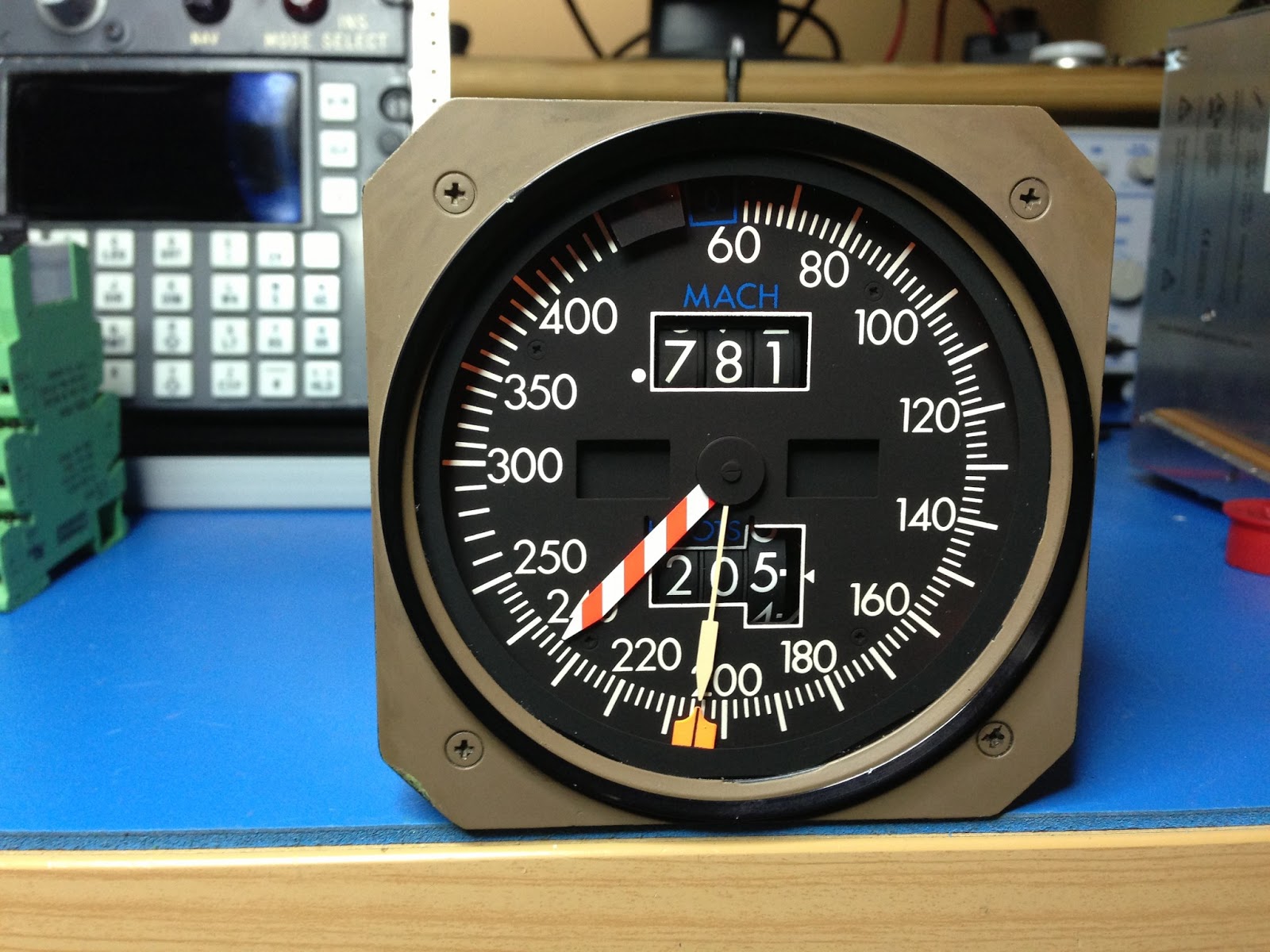
Avionics bending: Mach/Airspeed indicator

Hello everybody, following here is the pinout diagram of the 757 / 767 mach / airspeed indicator.


This is a very neat unit. It is powered at 115VAC 400Hz from Instruments Xfer Bus and it features dual source ARINC bus. The data in the plane come from the ADCs (Air Data Computer) which compute various parameters such as static pressure, dynamic pressure, altitude and Others and compute the arinc words to drive the gauge for the following functions:

- Airspeed
- Barber Pole
- Mach number

The Speed command bug is also in ARINC format and is directly driven by the MCP (Mode Control Panel)

Here are shots and a small test video of the unit. Enjoy!