Sections

mercoledì 17 settembre 2014

Avionics bending: Compartement Temperature Indicator


The primary (zone)temperature indication system is used to display the compartment and duct temperatures for the flight deck zone, forward zone, and aft zone.

The temperature indication system for each zone consists of a compartment temperature indicator, a compartment temperature bulb, a duct temperature bulb.

The compartment temperature indicator is located in the flight compartment near the air conditioning control panel, and has three liquid-crystal-display (LCD) readouts to display the temperature (1 to 99-degrees) in each of the three zones.
Twenty-eight volt dc power operates the compartment temperature indicator. The indicator sends a reference voltage through each compartment temperature bulb. The resistance through each temperature bulb varies with temperature and the signal then returns to the indicator. Thus the voltage level returning to the indicator produces the temperature readout corresponding to the actual compartment temperature.
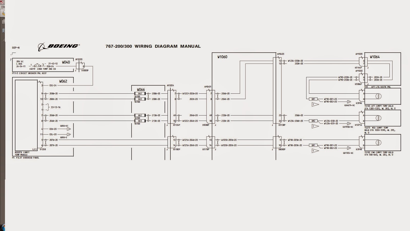
Following the schematic and wiring diagram of the unit


The following picture shows the temp indicator with power still on, but no signal from the sensors.


In the following picture I simulated a sensor using a 100 ohm resistor for each compartement which gives a readout of 22°Celsius


martedì 8 luglio 2014

Avionics bending: Mode Control Panel (MCP)

Hello people, sorry for the long time but I've been really busy with lot of stuff and had no time to make posts...

Anyway here I will show you one of the most used parts by the pilots those days, the MCP.

The MCP sends and receive data to/from many equipements, mainly involved are the 3 FCC (Flight Control Computers) and the TMC (Thrust Management Computer) and it's only a part of the Autoflight system.
The following scheme simplifies the interaction between the various equipements operating the autoflight functions.


The MCP has 3 connectors in the back which directly correspond to the 3 channels it operates (L, C, R)

The following pictus shows internal autopilot block scheme and the connections that each channel features


As you can see the MCP operates with 28VDC and a simple power up test allows some functions to work as you can see in the following video:


The following video shows the Airspeed's Speed Bug driven from the MCP dedicated ARINC channel


venerdì 7 marzo 2014

Avionics bending: Engine Standby Indicator

Hello people. I finally am the owner of a very neat unit, the engine standby indicator from a B767-200 used along with CF6-80A2 engines.
I did a did power up test with 28VDC and used its internate BITE test function to chech the unit was workin as expected.
Here is the schematic of the unit


and here are few pics and a video of it running, enjoy!


domenica 4 agosto 2013

Avionics Bending: EFIS Control Panel

Hello here we'll talk about the Captain and FO EFIS Control panels.


Those panels are mounted in the Throttle quadrant stand (P10) left and right of the lever block.

The unit is powered by 115VAC 400Hz provided by Captain Instrument Xfer bus bus for captain and FO Instrument Xfer bus for First Officer.
The power part include 5VAC lighting, DC and chassis GND and announciators BRT/DIM and TEST


The unit features 2 potentiometers that directly act on brightness for respective ADI and EHSI displays. The EHSI one is dual concentric to control also the balance of the screen as you can state from following diagrams:
 
EHSI
ADI
 

In the second picture you can note the connection between the control panel and the ADI display;
on the right you can also note the primary ARINC transmission channel which will transmit the DH set on the display as well as the range, mode and display options (ARPT,NAVAID,RTE DATA, WPT) selected on the panel.
The display mode (MAP,PLAN,VOR,ILS) is also sent out with discretes to interface to other equipemens like the VOR tuning panel as you can see in the following diagram:

 
The WXR display is set on as a discrete interfaced to the weather radar control panel located in the pedestal stand (P8)
 

Here is a video of power up test. Enjoy!