It needs 2 OC display cards to work along with 2 inputs for the switch, some outputs of the mastercard for the decimal points, a 5V source for backlight and you are ready to use it :)
venerdì 23 dicembre 2011
Engine Standby Gauge board
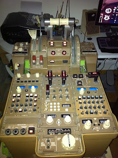
I am really proud to be able to show my 1st work in board design that has been focused on the B767 engine standby gauge. Following here are few images and link to a Video of it during work :)
It needs 2 OC display cards to work along with 2 inputs for the switch, some outputs of the mastercard for the decimal points, a 5V source for backlight and you are ready to use it :)
It needs 2 OC display cards to work along with 2 inputs for the switch, some outputs of the mastercard for the decimal points, a 5V source for backlight and you are ready to use it :)
venerdì 7 ottobre 2011
Spoiler Automation
Hello there!
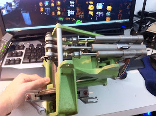
It finally seems that the Autospoiler modification of the real unit has finished givin a good result!
As you can see in the pictures, I replaced one of existing LVDTs with a spring loaded linear motion potentiometer.
I kept the rod end of the LVDT unit, bored it out, then I fitted the pot arm inside it and sealed with silicon (Liquid metal could be used too but silicon leaves flexibility of the arm to the rod end, plus the force during extension is made by the built in spring of the pot)
In the next picture you can see 2 wires coming out of the stock motor/generator: it features a DC motor operating at 28V and a generator with a built in brake.
What I did is remove the compression spring that keeps the generator brake rotating along the DC motor reducing the force needed by the DC motor to move the actuator.
I resoldered the wires at the ends of the DC motor and it spins pretty fast, and anyway close enough to the real speed.
CALL &AN_CONFIG
}
CALL &Spoiler_Logic
CALL &Spoiler_Ctrl
}
CALL &Spoiler_Logic
CALL &Spoiler_Ctrl
}
Var 9004, name Spoiler_Logic, Link SUBRUTINE
{
C0 = &Eng1Lever < 500 // engine 1 lever close to idle
C1 = &Eng2Lever < 500 // engine 2 lever close to idle
IF C0 AND C1
{
IF &GNDFLTOffst = 1 // aircraft on ground
{
C0 = &SPDBRKrev_SW = 1
C1 = &SpdBrkArm_SW = 1
IF C0 OR C1
{
&SpoilRellogic = 0 // set relays for the DC motor polarity set to spin motor to DOWN if powered
&SpoilerObj = 16384
}
ELSE
{
&SpoilRellogic = 1 // set relays for the DC motor polarity set to spin motor to UP if powered
&SpoilerObj = 0
}
}
ELSE
{
&SpoilRellogic = 1
&SpoilerObj = 0
}
}
ELSE
{
&SpoilRellogic = 1
&SpoilerObj = 0
}
}
&SpoilRel1 = CHANGEBIT 0 &SpoilRellogic
&SpoilRel2 = CHANGEBIT 0 &SpoilRellogic
}
C0 = &Bus_Left = 0 // Left BUS unpowered
C1 = &LeftHydPress < 1500 // Left system HYD pressure below 1500 PSI
IF C0 OR C1
{
&SpoilPWRrel = 0 // Spoiler power relay open
}
ELSE
{
IF &GNDFLTOffst = 0 // aircraft in flight condition
{
&SpoilPWRrel = 0 // Spoiler power relay open
}
ELSE
{
C0 = &SPDBRKrev_SW = 1
C1 = &SpdBrkArm_SW = 1
IF C0 OR C1
{
L0 = &SpoilerObj - &SpBrPosOffst
L1 = 0
IF L0 <> 0
{
L1 = 1
}
L0 = ABS L0
L2 = L1
IF &SpoilerObj = &SpBrPosOffst
{
L2 = 0
}
&SpoilPWRrel = L2
}
ELSE
{
&SpoilPWRrel = 0
}
}
}
}
CALL &Spoiler_Ctrl
}
Var 9010, name SpoilRel2, Link USB_RELAYS, Device 12, Output 5 // 2nd DC current polarity relay
It finally seems that the Autospoiler modification of the real unit has finished givin a good result!
As you can see in the pictures, I replaced one of existing LVDTs with a spring loaded linear motion potentiometer.
I kept the rod end of the LVDT unit, bored it out, then I fitted the pot arm inside it and sealed with silicon (Liquid metal could be used too but silicon leaves flexibility of the arm to the rod end, plus the force during extension is made by the built in spring of the pot)
In the next picture you can see 2 wires coming out of the stock motor/generator: it features a DC motor operating at 28V and a generator with a built in brake.
What I did is remove the compression spring that keeps the generator brake rotating along the DC motor reducing the force needed by the DC motor to move the actuator.
I resoldered the wires at the ends of the DC motor and it spins pretty fast, and anyway close enough to the real speed.
Here is a video of the lever actuated by setting idle reverse and spinned back by increasing (via keyboard as the throttle levers are still not interfaced) the thrust out of idle.
When it moves from armed it stopped earlier cause of an initial error in programmation, it works fine now :)
Following here is the logic I made for the most correct operation possible according to the real unit manual.
Var 8999, name SpdBrkTOcfg_SW, Link IOCARD_SW, Device 10, Input 29, Type I
{CALL &AN_CONFIG
}
Var 9000, name SPDBRKrev_SW, Link IOCARD_SW, Device 10, Input 206, Type I // idle rev detection switch that raises the spoiler lever from the DOWN detent
{CALL &Spoiler_Logic
CALL &Spoiler_Ctrl
}
Var 9001, name SpdBrkArm_SW, Link IOCARD_SW, Device 10, Input 31, Type I //spoiler arm detection switch
{CALL &Spoiler_Logic
CALL &Spoiler_Ctrl
}
Var 9002, name SBrkAbrkDis_SW, Link IOCARD_SW, Device 10, Input 30, Type I
{
C0 = &Eng1Lever < 500 // engine 1 lever close to idle
C1 = &Eng2Lever < 500 // engine 2 lever close to idle
IF C0 AND C1
{
IF &GNDFLTOffst = 1 // aircraft on ground
{
C0 = &SPDBRKrev_SW = 1
C1 = &SpdBrkArm_SW = 1
IF C0 OR C1
{
&SpoilRellogic = 0 // set relays for the DC motor polarity set to spin motor to DOWN if powered
&SpoilerObj = 16384
}
ELSE
{
&SpoilRellogic = 1 // set relays for the DC motor polarity set to spin motor to UP if powered
&SpoilerObj = 0
}
}
ELSE
{
&SpoilRellogic = 1
&SpoilerObj = 0
}
}
ELSE
{
&SpoilRellogic = 1
&SpoilerObj = 0
}
}
Var 9005, name SpoilRellogic, Link SUBRUTINE
{&SpoilRel1 = CHANGEBIT 0 &SpoilRellogic
&SpoilRel2 = CHANGEBIT 0 &SpoilRellogic
}
Var 9006, name Spoiler_Ctrl, Link SUBRUTINE
{C0 = &Bus_Left = 0 // Left BUS unpowered
C1 = &LeftHydPress < 1500 // Left system HYD pressure below 1500 PSI
IF C0 OR C1
{
&SpoilPWRrel = 0 // Spoiler power relay open
}
ELSE
{
IF &GNDFLTOffst = 0 // aircraft in flight condition
{
&SpoilPWRrel = 0 // Spoiler power relay open
}
ELSE
{
C0 = &SPDBRKrev_SW = 1
C1 = &SpdBrkArm_SW = 1
IF C0 OR C1
{
L0 = &SpoilerObj - &SpBrPosOffst
L1 = 0
IF L0 <> 0
{
L1 = 1
}
L0 = ABS L0
L2 = L1
IF &SpoilerObj = &SpBrPosOffst
{
L2 = 0
}
&SpoilPWRrel = L2
}
ELSE
{
&SpoilPWRrel = 0
}
}
}
}
Var 9007, name SpoilerObj
{CALL &Spoiler_Ctrl
}
Var 9008, name SpoilPWRrel, Link USB_RELAYS, Device 12, Output 3 // Spoiler power relay
Var 9009, name SpoilRel1, Link USB_RELAYS, Device 12, Output 4 // 1st DC current polarity relayVar 9010, name SpoilRel2, Link USB_RELAYS, Device 12, Output 5 // 2nd DC current polarity relay
sabato 27 agosto 2011
Flap position transmitter
I just completed the mod to the stock flap position transmitter unit.
Orignal part was equipped with a resolver to transmit the position to the flap position receiver unit. I took it out, fitted a potentiometer and cutted the out enclosure to place the pot on.
Here are few pics:
Orignal part was equipped with a resolver to transmit the position to the flap position receiver unit. I took it out, fitted a potentiometer and cutted the out enclosure to place the pot on.
Here are few pics:
giovedì 28 luglio 2011
Spoiler automation
Thanks to a deal obtained few months ago with my friend Victor, I have now in hand the autospoiler control unit. I am working to modify the unit to work with a DC motor instead of the stock AC motor generator and replacing one of the stock LVDT with linear motion potentiometer. Me, Philip, Valerio and Victor will work together to develop a structure based on the stock model to fit aftermarket linear actuators with integrated pots so, since we are all owners of the real Throttle quadrant, we will have it functional as the real one. Here is a first result of the lever movement. there will be an update as i'll find a suitable potentiometer to fit in order to test some sioc code I started to program. Stay tuned!
lunedì 25 luglio 2011
Flap Gauge
Hello, I finally finished the Flap gauge conversion started from an old boeing 727 flap gauge.
The conversion consisted in removing the existing resolvers and replacing one of them with a pot with dual side shaft: to the front shaft is directly connected the flap needle and to the back is connected a motor with planetary gear reduction. I used a kit from Tamiya which was very useful and cheap!
The front face has been made by my friend Valerio on the specs of the existing face to fit the chassis and with the 767 side crown raised. a wonderful job!!
Here are 2 pics of it at natural and lighted and following a video of it workin:
martedì 19 aprile 2011
ADI, ND and EICAS Displays
Finally i found some suitable LCD displays to use with EICAS, ADI and ND.
EICAS screens are 8" horizontally placed, ND are 8" vertically mounted and ADI is 6.4".
I couldn't resist to make a first test to verify that everything will go the right way and here is the 1st test result:
EICAS screens are 8" horizontally placed, ND are 8" vertically mounted and ADI is 6.4".
I couldn't resist to make a first test to verify that everything will go the right way and here is the 1st test result:
I will be using 3 video cards GTS250 for EICAS monitors and CPT and FO PFD and ND monitors
FMC will be via Parallax card so USB to TVout connection
mercoledì 9 febbraio 2011
Iscriviti a:
Commenti (Atom)


.jpg)


